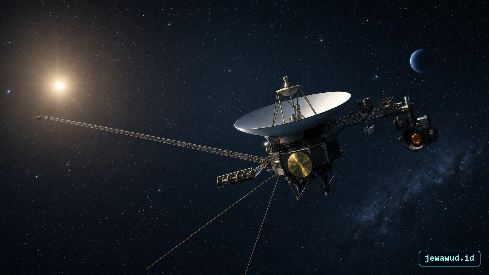
 Voyager's recognizable shape is driven by communication, power, and science needs
01Two Spacecraft, Two Different Routes
Voyager is a pair of spacecraft, not one probe that visited every outer planet. Voyager 2 launched on August 20, 1977; Voyager 1 followed on September 5 but took the faster route to Jupiter. Both encountered Jupiter in 1979. Voyager 1 reached Saturn in November 1980, while Voyager 2 arrived in August 1981.
The important fork was at Saturn. Voyager 1's close encounter with Titan helped send it out of the main planetary plane. Voyager 2 continued toward Uranus in January 1986 and Neptune in August 1989. Those destinations were not interchangeable stops on a route that could be changed at any time. They depended on the encounter geometry. NASA's mission fact sheet records the two paths.
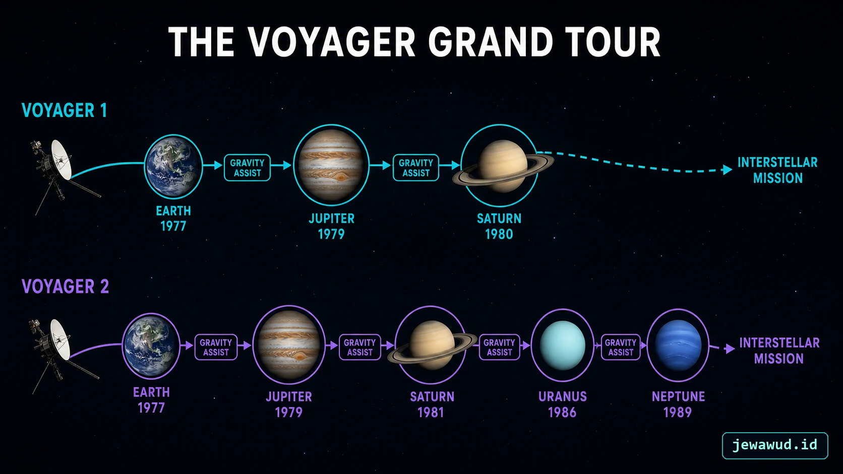 Gravity assists created two different routes: Voyager 1 toward interstellar space and Voyager 2 past all four giant planets
02Read The Hardware By Its Job
The 3.7-metre high-gain antenna is the radio link to Earth. The ten-sided bus beneath it houses electronics and other spacecraft systems. Three radioisotope thermoelectric generators supply electricity, while instruments on booms and a scan platform perform different kinds of science.
Voyager uses three-axis attitude control to orient the spacecraft and keep its antenna pointed appropriately. The scan platform can aim instruments without making every observation depend on the same body direction. NASA distinguishes ten physical science instruments from eleven investigations because radio science also uses the communications system. These are different ways of counting the payload, not conflicting inventories. NASA's spacecraft description identifies these systems.
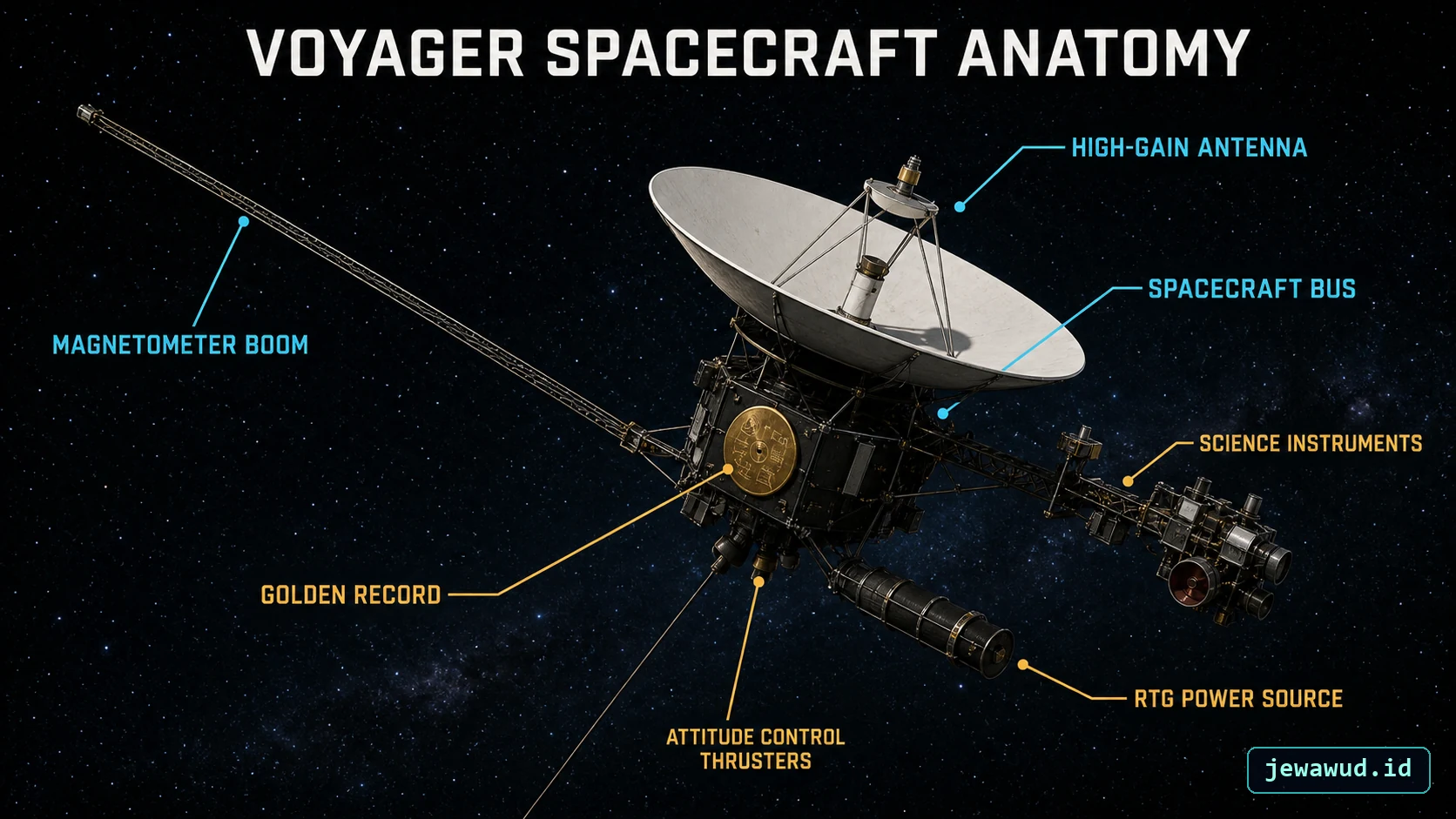 Voyager's dish, booms, science instruments, and RTGs are arranged around communication, stability, and isolation needs
03Why Put A Sensor On A Long Boom?
A magnetometer must measure the surrounding magnetic field rather than mainly the field produced by nearby spacecraft equipment. Moving it away from the bus helps separate the measurement from the machine carrying it. NASA describes Voyager's magnetometer boom as a deployable structure that unfolded after launch. NASA's engineering notes explain that arrangement.
This suggests a useful way to inspect the model: do not treat every protruding part as an antenna. Ask whether it sends a signal, receives radiation, supplies power, or supports another instrument. Similar-looking rods can have quite different purposes.
04Power Is A Budget, Not Just A Battery
Voyager's generators draw on radioactive-decay heat rather than sunlight. NASA lists three Multi-Hundred Watt RTGs per spacecraft; each produced approximately 158 watts of electricity at launch. That historical value is not today's available power. NASA's radioisotope mission records give the launch context.
When the supply falls, operating choices have to change. Keeping the transmitter, thermal protection and selected science measurements within the available budget can require other loads to stop. An instrument visible on a model is therefore not necessarily an instrument still collecting data. The detailed mechanism and power losses are covered separately in Heat Into Watts.
05Interstellar Space Is Not The End Of Solar Gravity
Voyager 1 crossed the heliopause in 2012; Voyager 2 crossed in November 2018. The heliopause marks a boundary between the solar-wind bubble and the surrounding interstellar medium. It is not a wall where the Sun's gravity switches off.
NASA's announcement of Voyager 2's crossing explicitly distinguishes leaving the heliosphere from passing beyond the much more distant Oort Cloud. This distinction prevents a common misleading caption: crossing into interstellar space does not mean escaping every region associated with the solar system.
06What A Measurement Can Tell Us
The interstellar transition was inferred from instruments, not recognized in a photograph of a visible border. In Voyager 1's case, plasma-wave observations helped establish that it had entered a denser plasma environment. NASA describes the evidence and the difficulty of interpreting it in its explanation of the crossing.
A mission overview should distinguish hardware, measurement and interpretation. The magnetometer measures a magnetic field; a camera records light; scientists combine observations to infer the environment. A decorative boundary on a 3D scene cannot replace that evidence.
07A Short Exercise In The Jewawud Model
Open Jewawud's Voyager 3D Explorer. In the assembled view, locate the dish and central bus. Rotate the model until you can distinguish the long boom from the shorter science structures. Then compare the exploded view with the assembled arrangement.
Try answering three questions: which system communicates with Earth, which supplies electricity, and which needs separation from spacecraft interference? Return to the assembled view before judging where parts sit. Exploded spacing is an inspection aid, not the configuration flown in space.
The model illustrates hardware; it does not report current attitude, instrument health or distance. For communication and navigation, continue with A Whisper Across Interstellar Space and Finding Voyager Without GPS.
SourcesSources And Scope
This overview uses the linked NASA/JPL mission histories and engineering descriptions. Encounter dates are historical milestones. Launch electrical output is labelled as such; no current instrument count, data rate or remaining lifetime is inferred from it. The illustrations and 3D model support identification, not engineering measurements.
Inspect Voyager
Compare the assembled spacecraft with its separated components.
Open Voyager 3D Page