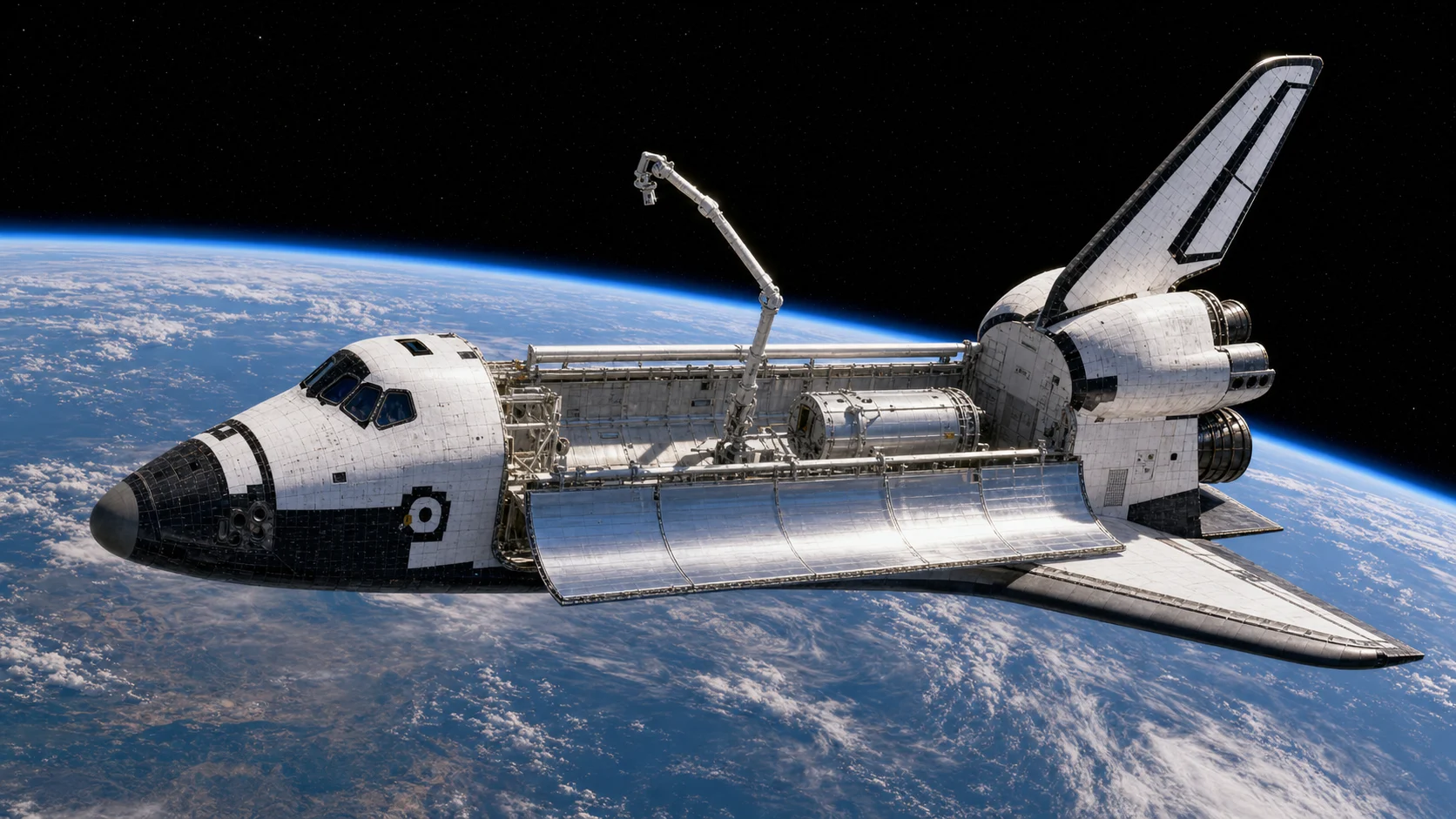
 The orbiter combined crew systems, cargo bay, maneuvering engines, and aerodynamic control surfaces
01Orbiter, Not Just Shuttle
When people say Space Shuttle, they often mean the orbiter: Columbia, Challenger, Discovery, Atlantis, or Endeavour. The full launch system included the orbiter, external tank, and solid rocket boosters. The orbiter was the winged spacecraft that carried crew and payload to orbit, returned through the atmosphere, and landed on a runway.
That hybrid role explains its unusual shape. It needed rocket engines for ascent, small thrusters for orbit, a payload bay for cargo, thermal protection for reentry, wings and elevons for landing, and crew systems for human operation. It was not a simple spaceplane. It was a compromise across many environments.
02Payload Bay Doors
The payload bay doors opened in orbit to expose cargo, experiments, radiators, and deployment hardware. They were not just doors. Their inner surfaces carried radiators that helped reject heat. Opening the bay was therefore part of thermal management, not only cargo access.
In a 3D model, open cargo bay views are valuable because they reveal the Shuttle's working interior. You can see why the orbiter was so useful for satellite deployment, retrieval, laboratory modules, and construction tasks. The payload bay made the Shuttle feel like an orbital workshop rather than a capsule.
03OMS Pods And Main Engines
At the rear of the orbiter were the orbital maneuvering system pods, usually called OMS pods. They housed engines used for orbit insertion adjustments, rendezvous support, and deorbit burns. Nearby were reaction control thrusters for attitude control. The three large Space Shuttle Main Engines were used during ascent while fed by the external tank.
This distinction matters when labeling a model. Main engines were not used like airplane engines after reaching orbit. OMS and RCS handled orbital maneuvering. The rear of the orbiter packed multiple propulsion functions into a dense region, which is why callouts must be placed carefully.
04RCS Thrusters
The reaction control system used small thrusters on the nose and aft sections to rotate and translate the orbiter in space. In orbit, aerodynamic surfaces do not work because there is no meaningful air. If the crew needed to change attitude, point the payload bay, perform rendezvous, or align for deorbit, thrusters did the job.
On a visual model, RCS modules are easy to miss because they are smaller than wings, engines, or doors. But they are essential spacecraft hardware. Without them, the orbiter could not precisely point itself in orbit.
05Wings, Elevons, And Body Flap
The orbiter's wings were not used to fly into orbit. They were used after reentry, when the spacecraft returned to the atmosphere as an unpowered glider. Elevons on the trailing edges helped control pitch and roll. The body flap behind the main engines helped protect the engines and control pitch during hypersonic reentry.
This is another place where aircraft intuition can mislead. The Shuttle did not cruise with engine power during landing. It descended steeply, managed energy, and landed without a go-around option. The aerodynamic surfaces were therefore part of a high-stakes return system, not ordinary airplane equipment.
06Thermal Protection
The black and white pattern on the orbiter was not styling. It represented different thermal protection materials used for different heating environments. The underside and leading edges faced intense reentry heating. Other areas needed insulation but did not experience the same peak loads.
Thermal protection made reusability possible, but it also required inspection and maintenance. On a 3D model, tile detail gives the Shuttle much of its character. More importantly, it reminds users that the orbiter survived reentry by managing heat, not by being simply strong.
07Landing Gear And Hatches
The Shuttle used nose and main landing gear for runway landing. The gear stayed stowed during ascent, orbit, and reentry, then deployed near landing. Side hatches supported crew ingress and egress. Flight deck windows gave the crew visibility for launch, orbit operations, rendezvous, and landing.
These details help make a model readable. Landing gear, hatches, and windows are human-scale features. When the scale feels wrong, the Shuttle stops feeling real. Accurate callouts and proportional framing make the viewer understand how large the orbiter was and where crew activity happened.
08Why Component Labels Matter
The Space Shuttle is a difficult object to label because many important systems are clustered together. The aft section contains main engines, OMS pods, aft reaction control thrusters, body flap, vertical tail, and elevons. The forward section contains cockpit windows, side hatch, nose RCS, nose landing gear doors, and thermal protection features. A callout placed only a little wrong can point to a different system.
This is why manual tagging can be useful. Automatic label placement often guesses based on bounding boxes or general geometry, but spacecraft parts are not evenly spaced simple objects. A human can identify the correct visual landmark and save that point. Once the tags are stored, the public version can hide tag mode and show only clean component selection.
A good component list should also avoid overwhelming the canvas. If every label appears at once, the orbiter becomes unreadable. A better interaction is: choose a component from the left panel, then show one focused callout on the model. The selected item can be highlighted, the description can update, and the camera can ease toward the relevant area. The user learns one part at a time instead of fighting a cloud of labels.
For Space Shuttle Parts, the interaction can be even stronger. Selecting a component can bring that component forward with independent rotate, drag, and zoom controls. That lets users inspect an EVA suit, docking system, engine, or landing gear without moving the whole scene. The key is isolation: the selected part should feel like a museum object on a turntable, while the full orbiter remains the context.
09Reading The Shuttle As A System
The orbiter makes more sense when each component is tied to a mission phase. Main engines belong to ascent. Payload bay doors belong to orbital operations and thermal control. RCS thrusters belong to attitude control in space. Thermal protection belongs to reentry. Elevons, body flap, rudder speed brake, and landing gear belong to atmospheric return and landing.
This phase-based reading prevents confusion. A wing is not useful in orbit. A payload bay door is not opened during ascent. Main engines are not used for final runway landing. The same vehicle changes identity throughout the mission: launch vehicle element, orbital spacecraft, reentry body, and glider. A strong 3D page should help the viewer feel those transitions.
That is also why descriptions should be precise. If a model shows Atlantis with an opened cargo bay, the text should not describe Columbia unless the page is intentionally discussing Columbia history. Visual identity and description must match. Small inconsistencies can make users distrust the rest of the model, even when the rendering is good.
10What To Inspect First
If you are opening the Shuttle model for the first time, start with the payload bay, aft propulsion area, nose section, and wing trailing edges. Those four zones explain most of the orbiter's mission personality. The payload bay shows cargo and orbital work. The aft area shows ascent and maneuvering systems. The nose shows crew scale and attitude thrusters. The wings show the return to atmosphere.
Then switch from whole-vehicle view to individual components. A landing gear part, EVA suit, docking adapter, or manipulator arm is easier to understand when isolated. The full orbiter gives context, but the isolated part gives detail. A strong educational page should let users move between those two modes without losing orientation.
For readers arriving from search, the key idea is phase awareness. The Shuttle's parts are easier to remember when each one is connected to ascent, orbit, reentry, or landing instead of listed as disconnected hardware.
FAQQuick Questions
Was the orbiter a rocket or airplane? It was both in different phases: rocket-powered during ascent as part of the launch stack, spacecraft in orbit, and glider during landing.
Why open the payload bay doors in orbit? For payload operations and thermal radiator exposure.
Did the main engines fire in orbit? The main engines were ascent engines. OMS and RCS handled orbital maneuvering.
Inspect The Orbiter In 3D
Open the Space Shuttle page and use component callouts to connect the article with the 3D model.
Open Space Shuttle 3D