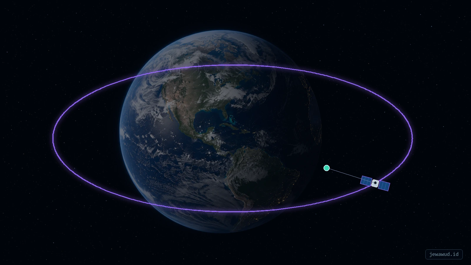
 A fixed orbital plane becomes a shifting track when projected onto rotating Earth
01What A Ground Track Actually Shows
JOT (Jewawud Orbital Tracker) is an interactive real-time satellite map developed by Jewawud Propulsion Laboratory. It uses TLE data and SGP4 propagation to display satellite positions, orbital paths, ground tracks, and telemetry around a three-dimensional Earth. This guide explains the ground-track patterns visible in JOT and other satellite-tracking applications.
A satellite ground track is the path traced by the point directly beneath a spacecraft on Earth's surface. That point is called the subsatellite point. If an imaginary line were drawn from the center of Earth through the satellite, the location where it intersects the surface would be the point plotted on the map.
This distinction matters because a ground track is not a side view of an orbit and it does not show the spacecraft's altitude. It compresses a three-dimensional position into latitude and longitude. Two satellites can cross the same point on a map while flying at very different altitudes, speeds, and times.
Trackers such as JOT calculate the spacecraft position for a sequence of timestamps, convert those positions into Earth-fixed coordinates, and connect the resulting subsatellite points. The familiar curve is therefore a time-ordered projection, not a physical trail left behind the spacecraft.
02Why The Path Looks Like A Wave
Imagine a circular orbit as a tilted ring around a globe. The satellite moves smoothly through that orbital plane, but a rectangular world map stretches the spherical Earth into a flat surface. Latitude rises as the spacecraft travels north, reaches a maximum, falls through the equator, reaches a southern minimum, and rises again. On a flat map, that repeated north-south motion resembles a sine wave.
The wave is a consequence of geometry and map projection. The spacecraft is not steering left and right in space. In an idealized two-body orbit, it follows a smooth ellipse in one plane while Earth turns beneath it.
The ends of a rectangular map also create a visual discontinuity. When longitude passes 180 degrees east or west, the plotted line wraps to the opposite edge. A line that appears broken at the map boundary is usually continuous around the globe.
03Inclination Sets The Latitude Limits
For a prograde orbit with an inclination below 90 degrees, the ground track normally reaches latitudes approximately equal to the inclination. The International Space Station, with an inclination near 51.6 degrees, travels between roughly 51.6 degrees north and 51.6 degrees south. It does not pass directly above locations farther poleward.
A near-equatorial orbit produces a narrow wave close to the equator. A near-polar orbit reaches close to both poles and can eventually observe most of Earth as the planet rotates. Retrograde orbits use inclinations above 90 degrees, but their latitude limit is interpreted through the geometry of the orbital plane rather than by treating a value such as 98 degrees as a reachable latitude.
Inclination tells you the north-south envelope, but it does not tell you how frequently a place is visited. Revisit time also depends on altitude, orbital period, sensor field of view, constellation size, and whether the ground track repeats.
04Earth Rotation Shifts Every Pass
The orbital plane of a low Earth satellite remains nearly fixed in inertial space over a short time, while Earth rotates eastward underneath it. By the time the satellite completes one orbit, Earth has turned through part of a rotation. The next ground track therefore crosses the equator at a different longitude.
For a roughly 90-minute low Earth orbit, Earth rotates about 22.5 degrees during one revolution. The exact spacing depends on orbital period and perturbations, but the principle is simple: the spacecraft returns to its orbital plane while a different part of Earth has moved below it.
On a typical map, successive prograde passes appear shifted westward. This is not orbital drift in the everyday sense. Much of the visible shift comes from the coordinate system rotating with Earth. This is also why a static orbit ring on a 3D globe and a moving ground-track line on a 2D map can both be correct.
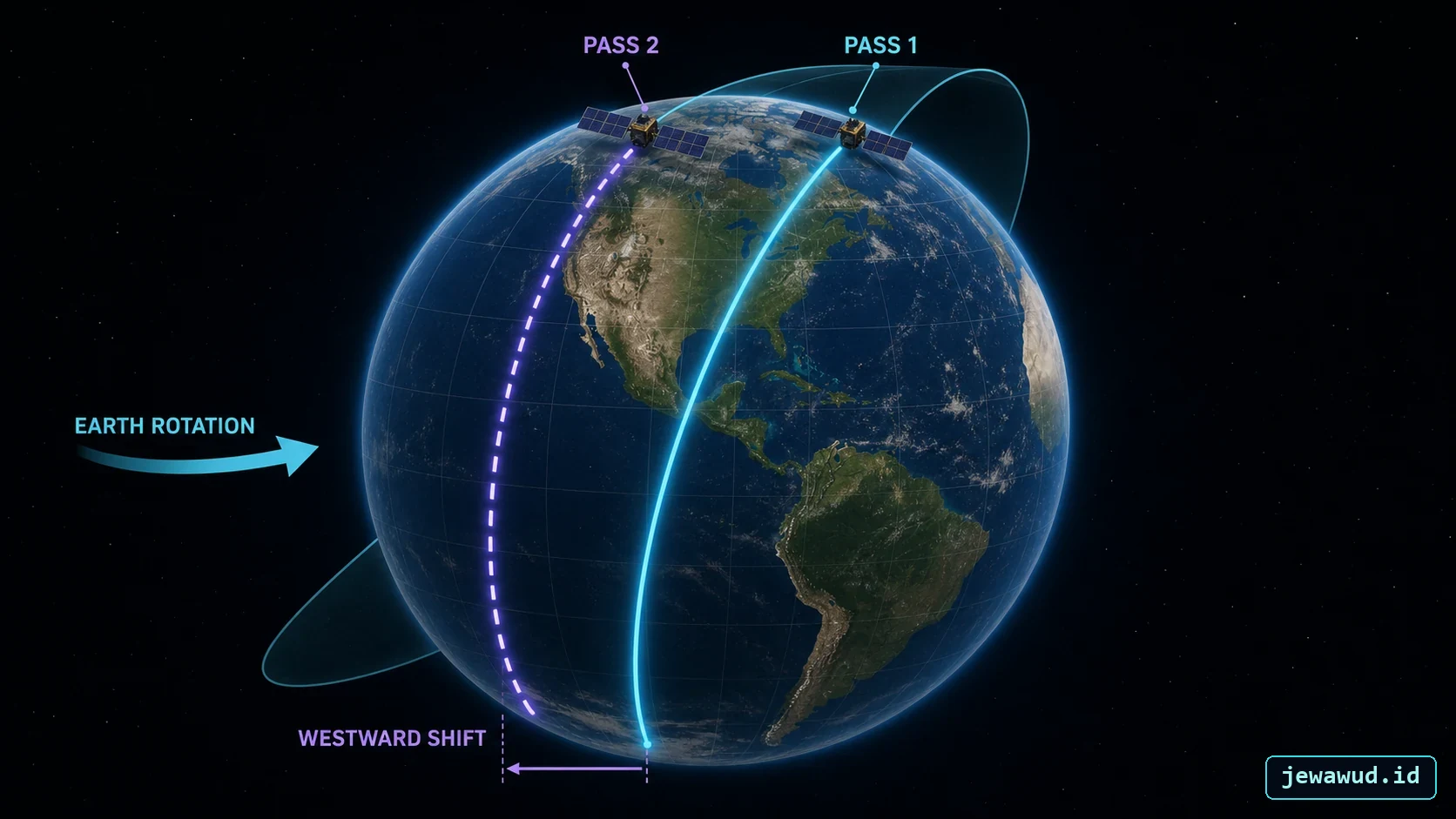 Earth turns eastward during each orbit, so the next surface path appears farther west
05Ascending And Descending Nodes
A ground track crosses the equator twice per orbit. At the ascending node, the spacecraft moves from the Southern Hemisphere into the Northern Hemisphere. At the descending node, it moves from north to south.
These crossings help operators read direction from a map. If the track climbs toward higher northern latitude as time advances, the satellite is on an ascending pass. If it falls toward southern latitude, it is descending. The longitude of the ascending node is also connected to the orientation of the orbit in space, commonly described with the right ascension of the ascending node, or RAAN.
RAAN is measured in an inertial reference frame, while map longitude belongs to an Earth-fixed frame. Converting between them requires the current orientation of Earth, which is why accurate timestamps are essential for a tracker.
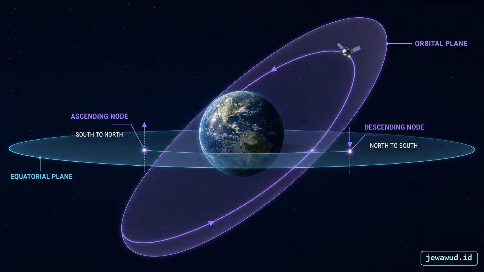 Nodes are the two exact intersections between the orbital plane and Earth's equatorial plane
06Past, Present, And Predicted Track Segments
Satellite maps often draw a line before and after the current marker. The segment behind the marker represents previously propagated positions. The segment ahead represents predicted positions generated from the same orbital model. Neither segment is a permanent object in space; both are sampled positions associated with timestamps.
The displayed prediction window matters. Showing one orbital period gives a clean single loop, while showing several periods creates multiple shifted waves. A long window can look impressive but may become visually confusing, especially when thousands of satellites are present.
A good tracker distinguishes the selected satellite, its current position, and its predicted path without hiding the surrounding constellation. The path should begin at the selected object, follow the same coordinate transformation as the marker, and wrap correctly at the map boundary.
07Repeat Ground Tracks And Revisit Time
A repeat ground-track orbit is designed so that, after a particular number of revolutions and Earth rotations, the satellite returns close to an earlier path over the surface. This does not necessarily mean it returns to the same location on every orbit. The repeat may occur after several days and many revolutions.
Mission designers use repeat cycles for mapping, radar imaging, altimetry, and other observation tasks that benefit from consistent geometry. The orbital period must be chosen in relation to Earth's rotation, while perturbations and nodal precession must also be considered.
Revisit time is related but different. A sensor may observe the same area without flying directly over the same subsatellite path because it can look to either side of nadir. A wide-swath instrument can revisit a region sooner than the exact ground track repeats.
08Why GEO Looks Completely Different
A satellite in a circular geostationary orbit moves eastward above the equator with a period matched to Earth's sidereal rotation. Its subsatellite point remains near one longitude, so its ground track is essentially a point rather than a wave.
A geosynchronous satellite that is inclined or eccentric still shares Earth's rotation period, but its ground track can form a north-south figure eight called an analemma. Inclination produces the vertical motion, while eccentricity contributes east-west motion.
This gives a useful diagnostic rule: a broad repeating wave usually suggests a lower orbit viewed over one or more revolutions, while a compact figure eight suggests a geosynchronous orbit that is not perfectly geostationary.
09From TLE And SGP4 To A Line On The Map
JOT begins with orbital data such as a Two-Line Element set. The SGP4 propagator estimates the satellite state at a requested time in an Earth-centered inertial reference frame. The tracker then accounts for Earth's rotation, transforms the state into an Earth-fixed frame, and converts the result to geodetic latitude, longitude, and altitude.
Repeating this process across many timestamps creates the samples used for the ground track. The selected satellite marker and its orbit line must use the same time basis, reference frames, and longitude convention. If one uses inertial coordinates while the other uses Earth-fixed coordinates, the line may appear detached or on the opposite side of the planet.
TLE data is not a timeless description. Its epoch and the propagation interval matter. Predictions generally become less trustworthy as the TLE ages, particularly for low satellites affected by atmospheric drag and for spacecraft that maneuver.
10How To Read A Ground Track In JOT
Start with the current satellite marker, then follow the predicted line in its direction of travel. Check the highest northern and southern latitudes to estimate inclination. Observe where the line crosses the equator to identify ascending and descending passes. Finally, compare successive passes to see how far Earth rotates underneath each orbit.
Switch between the 3D globe and a map view when possible. The globe makes the orbital plane intuitive; the map makes geographic coverage and pass direction easier to compare. Neither view contains the whole story by itself.
In the Jewawud Orbital Tracker, categories such as GPS, weather satellites, Starlink, and geostationary spacecraft reveal different patterns. Selecting one object should preserve its current dot while adding a path that remains attached to it. That visual continuity is an important check that the propagation and rendering pipelines agree.
11Common Interpretation Mistakes
Mistake one: treating the line as altitude. A taller wave means greater latitude reach, not greater height above Earth. Altitude must be read separately.
Mistake two: assuming the satellite visits every place under the curve. The line marks the subsatellite point. Actual coverage depends on antenna or sensor footprint and the required elevation angle.
Mistake three: interpreting map-edge jumps as maneuvers. Longitude wraps at the antimeridian, so a continuous track can appear split.
Mistake four: expecting the next orbit to repeat the same line. Earth rotates during every revolution. Most low Earth ground tracks shift between passes.
Mistake five: trusting a long prediction without checking data age. Propagation quality depends on the orbit, elapsed time, maneuvers, drag, and the freshness of the source elements.
12Ground Track, Footprint, And Visibility Are Not The Same
The ground track is a single path of subsatellite points. A sensor footprint is the region an instrument can observe at a given moment. A visibility footprint describes where an observer could potentially see or communicate with the satellite above a chosen elevation limit.
These areas can extend hundreds or thousands of kilometers away from the ground track, especially at higher altitude. A satellite does not need to pass directly overhead to be visible. Likewise, being inside a theoretical footprint does not guarantee a useful radio link or image; terrain, atmosphere, antenna direction, lighting, and mission constraints still matter.
Keeping these three ideas separate prevents a map line from promising more coverage than the spacecraft can actually provide.
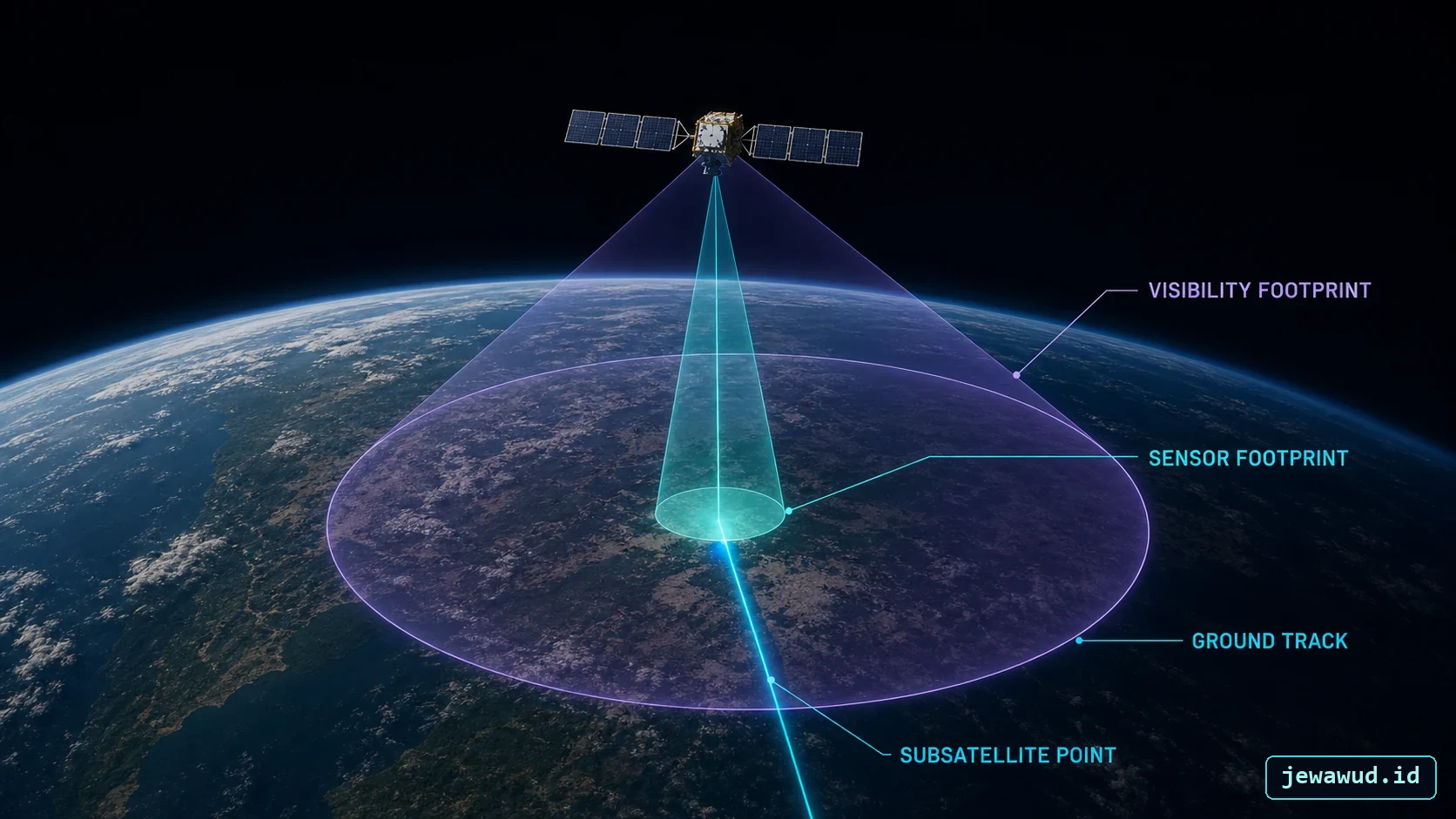 The ground track is a line; sensor and visibility footprints are areas with different limits
FAQQuick Questions
Why does a satellite track move west on the map? Earth rotates eastward beneath the orbit, so successive prograde passes usually appear at more westerly longitudes.
Does the wave show the satellite moving up and down? It shows changing latitude on a flat projection, not vertical altitude.
Why is a track broken at the edge of the map? The line crosses the antimeridian and wraps between +180 and -180 degrees longitude.
Can two satellites share the same ground track? They can cross similar latitude-longitude paths at different times or altitudes, but that does not mean their complete orbits are identical.
SourcesFurther Reading
This guide follows standard orbital-mechanics and tracking concepts described in CelesTrak's coordinate-system reference, NASA's Basics of Space Flight, and the European Space Agency overview of orbit types.
For the data and propagation pipeline behind modern trackers, continue with What Is TLE Data? and What Is SGP4?. For the orbital tilt that defines latitude reach, read Understanding Orbital Inclination.
Watch Ground Tracks Live
Select a satellite in JOT, keep its marker visible, and compare its 3D orbit with the shifting path projected across Earth.
Open Live Orbital MAP [JOT]